 English
 中文
中文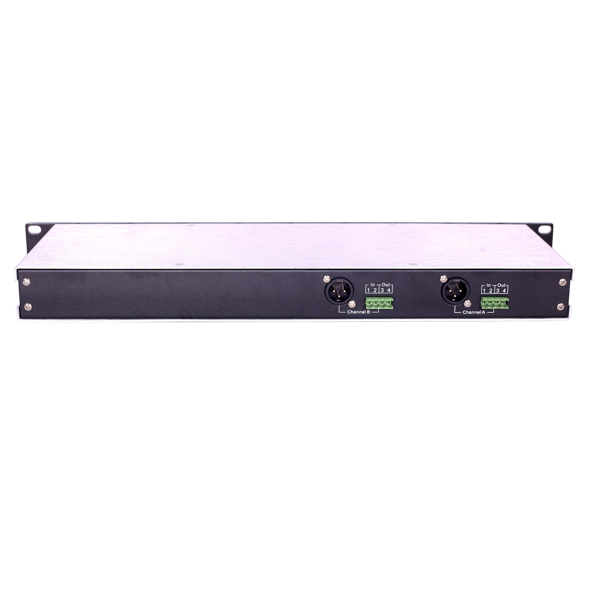
TF-204 2-Wire/4-Wire Interface
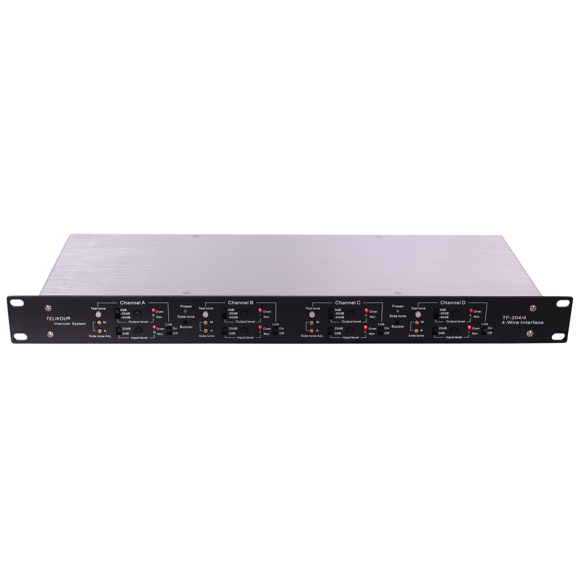
Two channel or 4 channel is optional
Input and out Level adjustment
The TF-204 4-wire interface is consisting of two units. Each unit has two independent sets of 2-wire / 4-wire connectors.
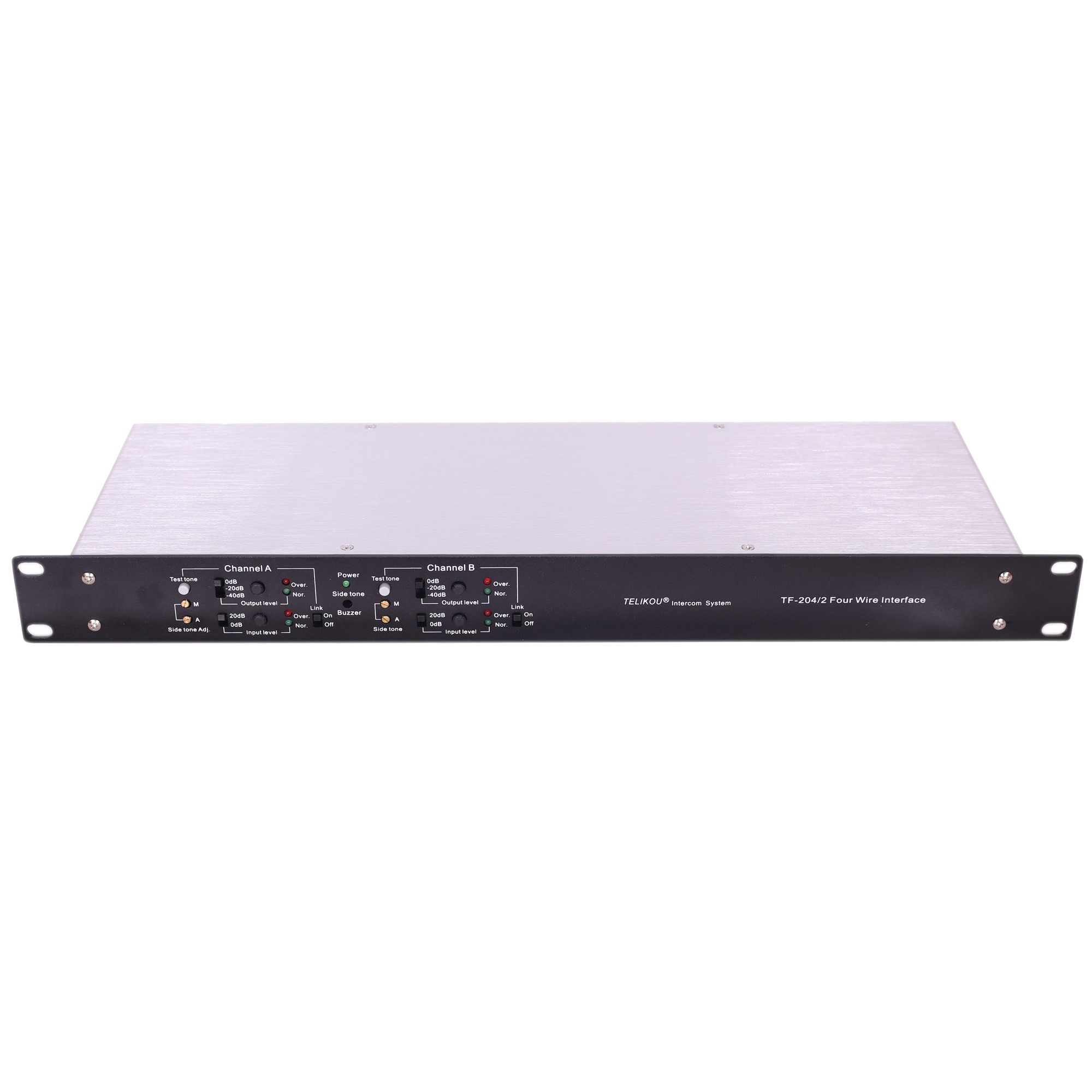
Front Panel
l Sidetone Adjustment
Unsatisfied sidetone could cause feedback between input and output. In either of these cases, you should minimize the amount of sidetone.
Sidetone Adjustment Procedure:
A) Set Link (5) switch to OFF.
B) Turn the Input Level Reduction Switch (8) to 0dB.
C) Press Test Tone (7) button, a constant beep sound can be heard from the Sidetone (6) Monitoring hole.
D) Adjust Output Level (9) control knob to make the beep level heard properly.
E) Turn the Main Sidetone Adjustment M (1) knob by clockwise and anti-clockwise direction slowly. Find minimum listening level.
F) Turn the Auxiliary Sidetone Adjustment A (1) knob. Find the minimum listening level.
Repeat this procedure A) to F) for other channels.
l Output Level
Output Level Reduction Switch (8)
This switch has 0dB, -20dB and -40dB three levels. It reduces the signal level which is sent to the pin3 and 4 of 4-wire connector (13) at rear panel.
Output Level Adjustment (9)
This output level adjustment provides a strong average green light on the Output Level Indicator (10). This occurrence indicates a 0dB line level on 600ohm line. Red light indicates exceeded output level. Occasional transitions to a red light are acceptable.
Output Level Indicator (10)
Green light indicates output level normal.
Red light indicates output level high.
l Input Level
Input Level Reduction Switch (2)
This switch has 0dB and -20dB two levels to match the signal level which is sent from pin1 and 2 of 4-wire connector (13) at rear panel.
Input Level Adjustment (6)
Adjust the Input channel gain to fit different input signal level. This knob provides a strong average green light on the Input Level Indicator (4). Meanwhile the level on pin3 of 2-wire connector is 0dB. Red light indicates exceeded input level. Occasional transitions to a red light are acceptable.
Input Level Indicator (4)
Green light indicates input level normal.
Red light indicates input level high.
l Link
Link (5)
Channel A and Channel B are individual to each other when this switch is set to the Off position.
When this switch is set to ON position, Channel A and Channel B are connected.
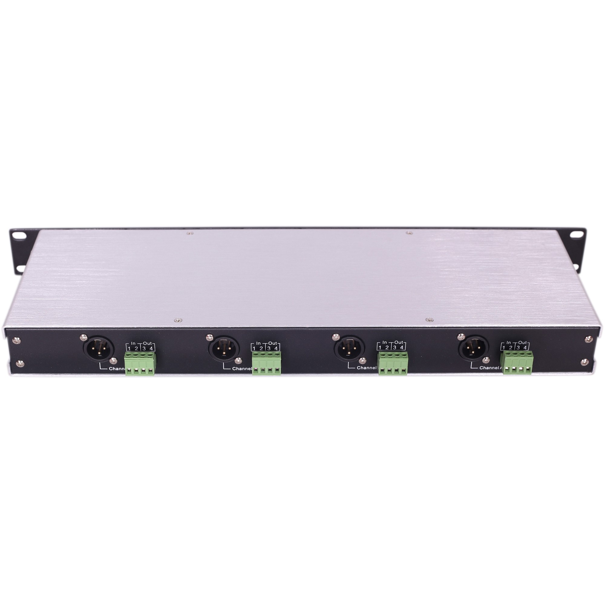
Rear Panel
4-wire In/Out Connector (8)
Input: Pin1 --- Audio+
Pin2 --- Audio- (Common)
Output: Pin3 --- Audio- (Common)
Pin4 --- Audio+
External signal to TF-204 can be balanced or unbalanced. Unbalanced signal is easier to bring in the noise, it is better to bring in balanced signal.
Intercom Line Connector (9)
3-pin XLR female socket
The pinout of the intercom connectors is as follows:
Pin 1 --- Common (Shield)
Pin 2 --- Power (15~30 VDC)
Pin 3 --- Audio
III. Installation
TF-204 adopts 19-inches 1U cabinet, and this workstation can be mounted on rack or placed on desktop. TF-204 uses standard 2-core shield cable. It can be powered by any channel or by A, B (A, B, C, and D) together.
Two XLR-3 connectors for channel A and B are used to connect 2-wire equipments. Pin connector is used to connect 4-wire input and output equipments.
IV Troubleshooting
Problem: System feedback (Acoustical)
Cause 1: Input or output signal level is too high
Solution 1: Adjust the signal level
Cause 2: Side tone of this station or any remote station is not adjusted correctly
Solution 2: Adjust side tone refer to the procedure in the Front Panel section of this manual.
Cause 3: No terminal in the system.
Solution 3: Check the terminal in the system.
Cause 4: 4-wire equipments connector are not connected well
Solution 4: Check the connection.
Problem: Output level is set to max, the audio level from camera end is still too low
Cause: Output level raw adjustment is not proper
Solution: Set output level raw adjustment to ‘Line’, then adjust output level to proper level
Problem: The audio level heard from camera end is too low
Cause: Input level is too low
Solution: Adjust input level by clockwise to proper level
Problem: Hum or buzz in system
Cause 1: Inductive pickup caused by close proximity of this main station or connected remote stations to power lines or transformers.
Solution 1: Relocate the offending unit.
Cause 2: Intercom line cable is not wired properly; the shield of microphone cable is not connected to Pin-1 of 3-XLR
Solution 2: Check intercom line cable. Make sure all the cables’ Pin-1 of 3-XLR connects correct.
V Technical Specification
Bandwidth:
300Hz – 4000Hz ±3dB
Input:
Balanced, unbalanced self-adaption
Resistance: >10K ohm Bridge
Level: -37dBu-+12dBu (1KHz)
Output:
Balanced, unbalanced self-adaption
Resistance: 600 ohm
Level: -43dBu - +8dBu (1KHz)
Environmental
0°-70°C(32°-158°)
Dimensions
19” (W) x 1.77” (H) x 6.69” (D), 483mm x 45mm x 170mm
Weight
1.9kg
Note: 0dBu=0.775V RMS


